

Ball & Plate Mechanical Development
The mechanical design process began by determining the most cost effective size. A search for the main component, the 4 wire touchscreen, yielded the lowest cost alternative that was still practical for the unit to work properly. The screen chosen is a 5.7” touchscreen that is as close to a square shape as I could find and yet is still compact to fit on a desktop. I also considered the cost of shipping and this size touchscreen allows the entire kit to fit neatly into a USPS priority small flat rate box Also it is a free box!
With the over-all size issue settled, the next major component is the attachment of the control plate to the top plate. This attachment must only have 2 degrees of freedom, roll and pitch. No other degree of freedom can be tolerated by the system, the other four degrees of freedom are x,y,z translation and yaw.
My first attempt at an attachment was to use a coil spring. I was very pleased with the simplicity of this in theory, and I had found a screw size that screwed directly into the spring itself. This made the spring solution very low cost. I designed and built a prototype, only to find that the spring concept was fundamentally flawed, it allowed the top plate to rotate about the spring axis (yaw) with little to no resistance. Abject failure
The next design, required a lengthy search to find a low cost universal joint. I found a few different small universal joints from the RC car industry. made from steel, stainless steel and brass None of these however, had a good way to attach to the control and top plate. I made a few tries with some straight shaft designs to take advantage of the RC design intent, but this did not work. I then found a universal joint that had about the right bore to tap at 3.5mm, an odd size of course. This joint also proved to be rather expensive along with the required secondary operation of tapping the bores
The next set of prototypes used the universal joint with tapped bores and screwed to the top and control plates. This also proved to have a huge amount of yaw. Either the single centered screw joint twisted, or the relatively small clearance of the universal joint itself, multiplied over the length and width of the plate size, was intolerable. Again, a complete failure
It was becoming very clear that the joint had to be very a very tight construction and as large as possible so that even a small amount of working clearance did not multiply to a large amount of yaw. It also had to be easy to assemble and low cost
The first idea was to use the laser process to create parts. For the first design, I used some 2mm stainless steel shafts I had purchased for another method of movement for the top plate which was abandoned This design worked, but required an accurate hole to be drilled in the four sides of the joint center. Way too much work and cost. The final universal instead used laser cut bearings and journals that require no secondaries other than the normal edge trimming
In all, it took fourteen iterations of the mechanical design to get the final kit configuration.
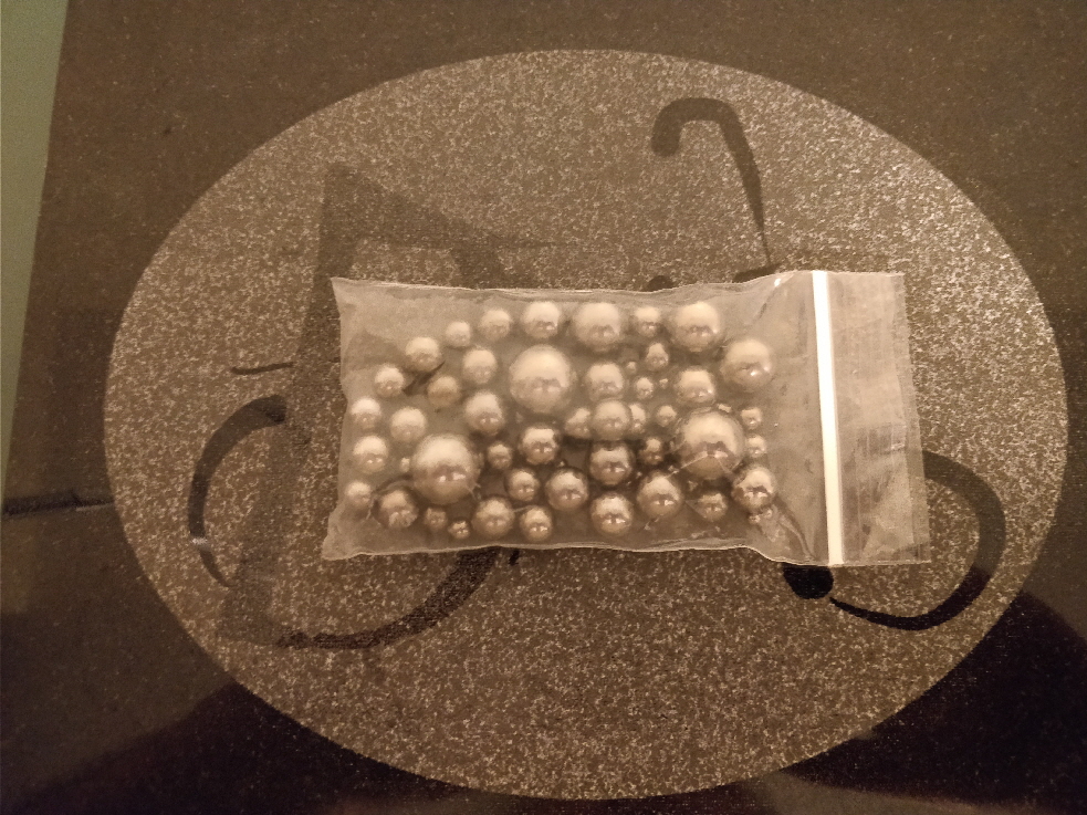 Experimented with many ball sizes
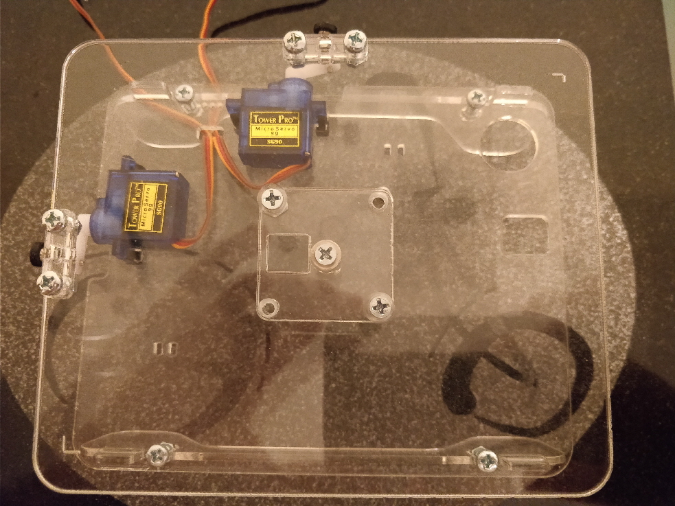 RC car drive shaft universal joint
 RC car drive shaft universal joint
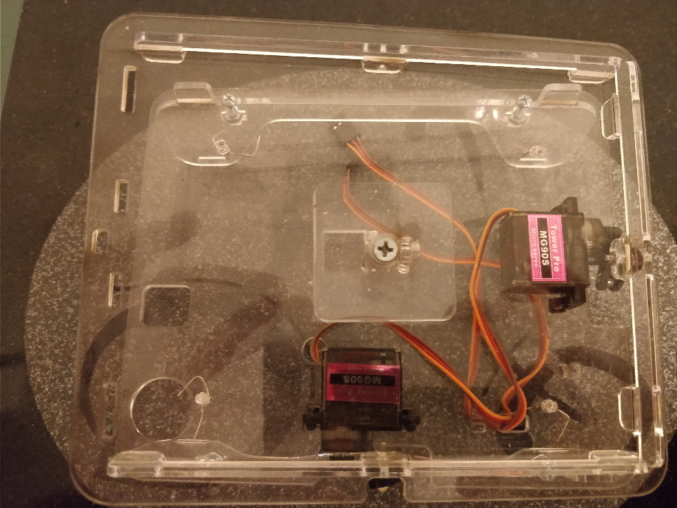 Digital servo
 RC car drive shaft universal joint with stabilizer
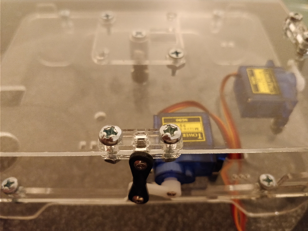 Link end reinforcement
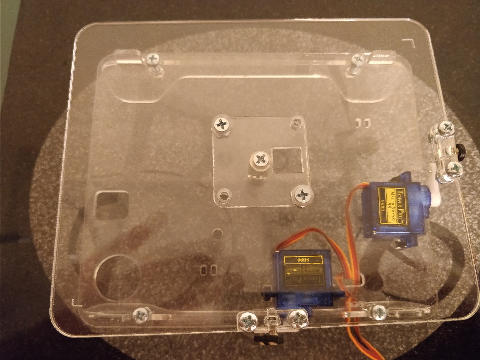 Link end reinforcement
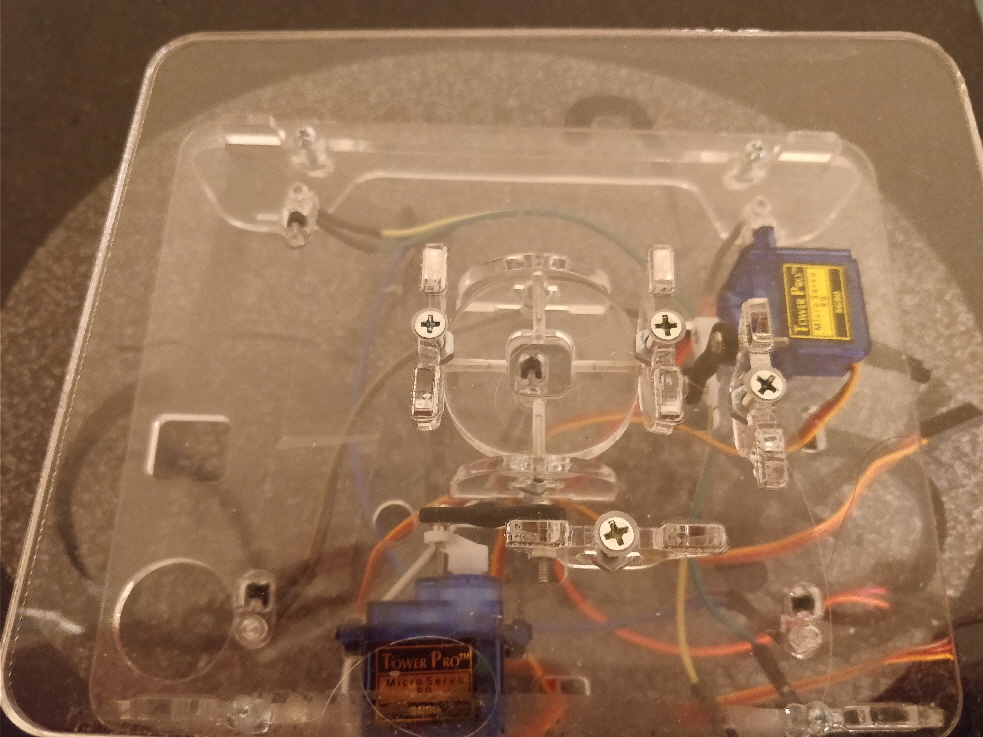 First try laser cut universal joint
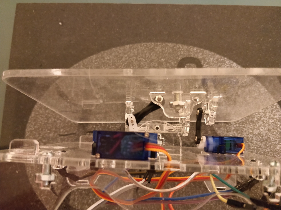 Final link end design
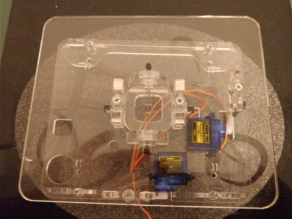 final laser cut universal joint
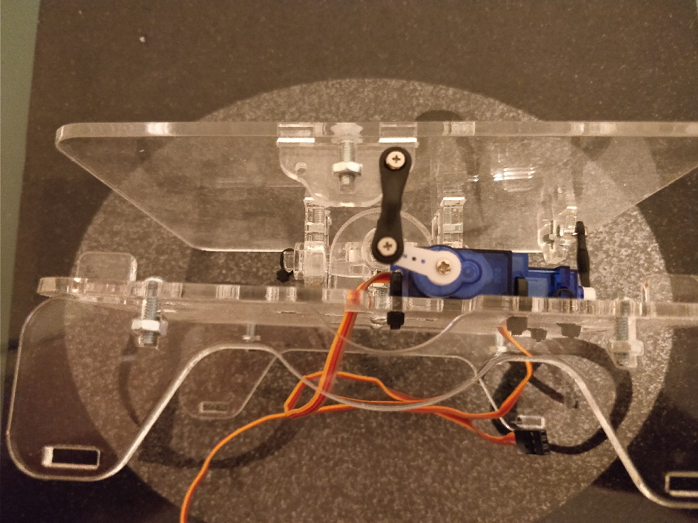 final laser cut universal joint
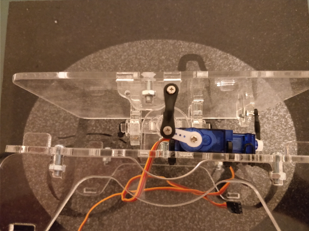 final laser cut universal joint
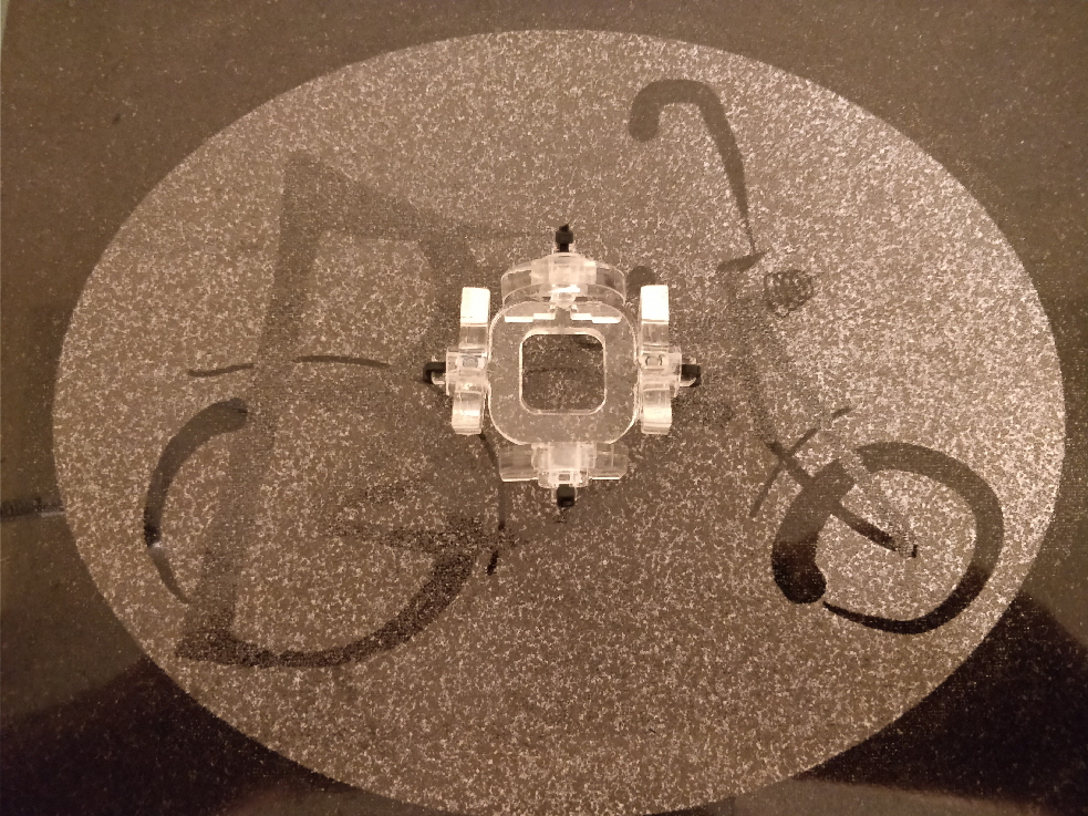 final laser cut universal joint
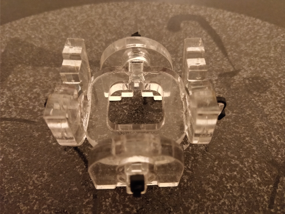 final laser cut universal joint


