


Ball & Plate Electronics Development
The electronics design process began with the Arduino Nano core. The first step was to get the system working in the most basic way. This was done with a wire socket breadboard. I was able to get the system talking to the Arduino, but the troubleshooting portion became difficult because the wires made bad or intermittent connections and this caused errors that were hard to identify. This phase did help to do the initial design, but moving past this phase as quickly as possible was the best path.
An interim solution was to use a small Arduino based shield containing terminal connectors for the Arduino pins, this worked very well electrically and allowed a much more robust initial design period. These small assemblies are available very cheaply and will be my starting point for future designs
The next step was to begin finalizing the PCBA size and layout. This was accomplished in two ways. First the components that were determined by the initial phase were assembled in Solidworks 3D to determine the best mechanical layout for the board size and connector location.
I found the closest size solder-able breadboard and made one prototype with this. At first I thought this would be the path for the final kit, but soldering this breadboard is a lot of work and it is easy to make a big mistake.
I decided to make a custom board, which I layed out in a similar fashion to the solder-able breadboard using a shareware tool called KiCad I have found that laying it out in .100” spacing aligned with the main components, in this case the Arduino pins is a common mistake for a first time board layout, mostly I think this is because it is hard to change from a Mechanical Engineer mindset to an Electrical Engineer mindset in the first go.
As you can see the connectors were very close together, this made terminating the wires in assembly very difficult. There is also a patch at pins D10 and D11 because I used two Arduino analog pins incorrectly when I added more LED’s without proper testing, another lesson learned
I have since done 2 more iterations or “spins” of the Plate & Ball PCBA, one to correct the 2 display pins that were wrong due to the addition of the LED’s and one because the drawing for the power supply was incorrect
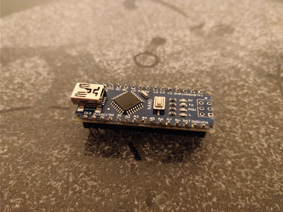 Arduino PCBA
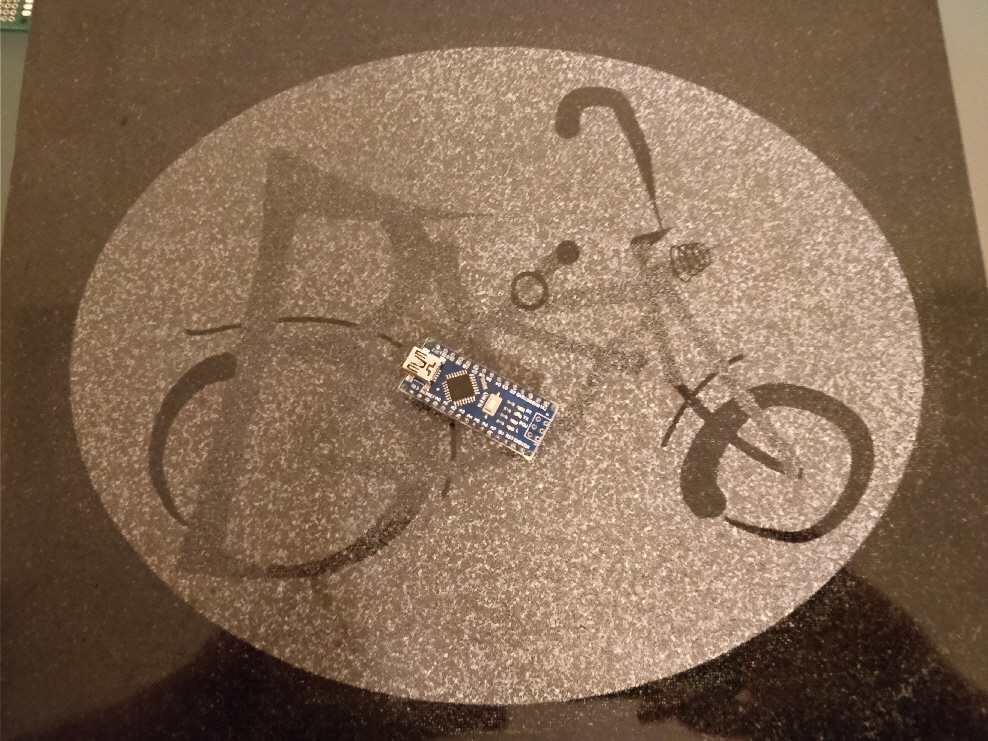 Arduino PCBA
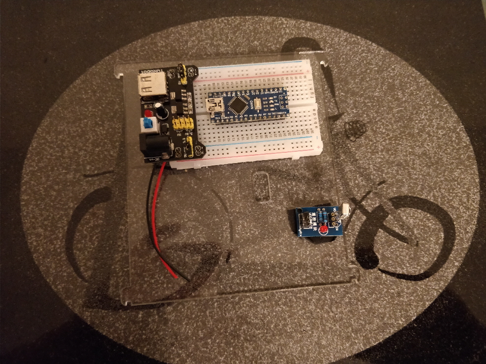 Breadboard construction
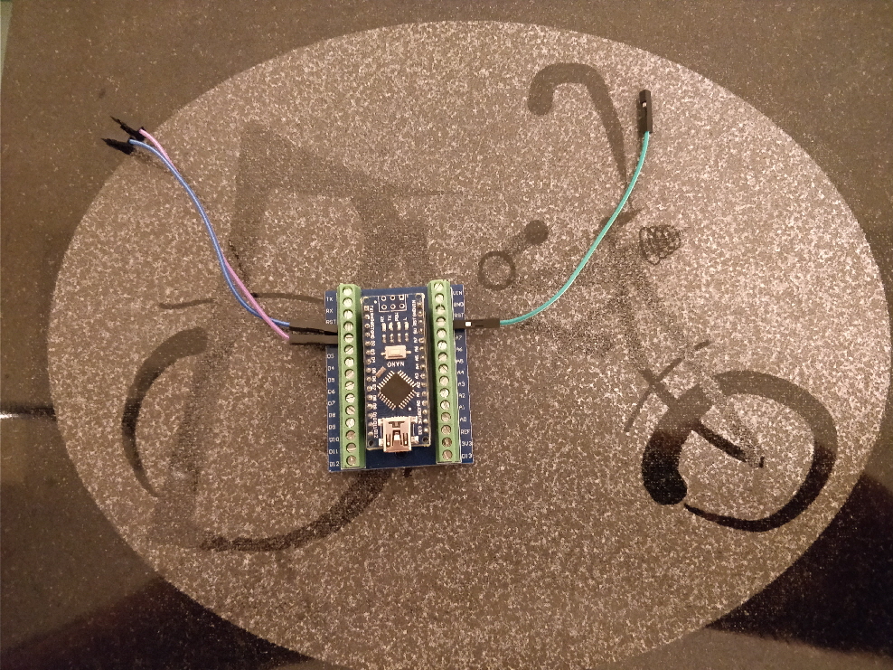 Alternative Arduino connection
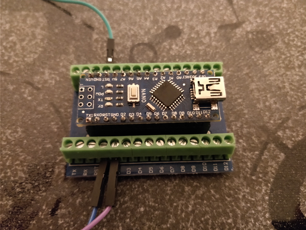 Alternative Arduino connection
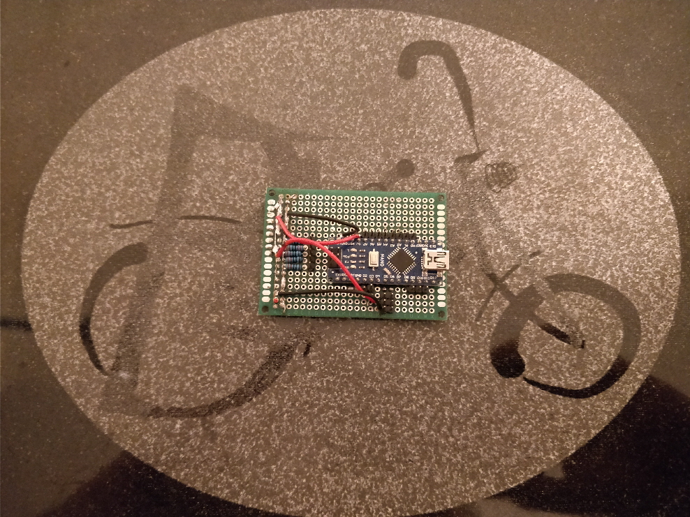 Soldered Breadboard construction
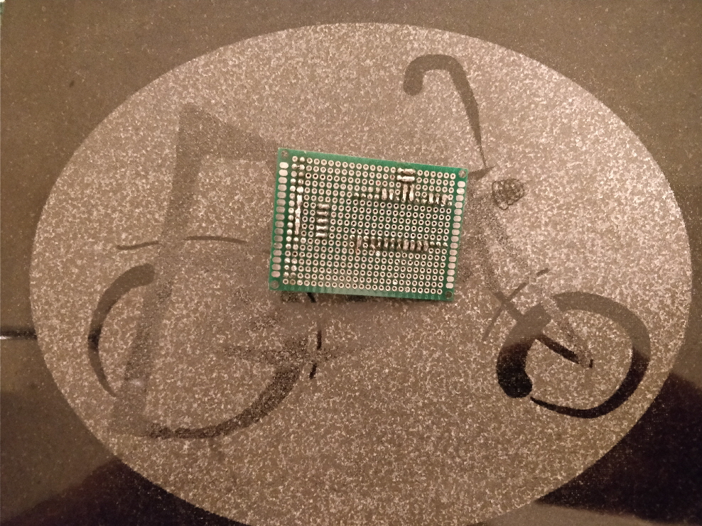 Soldered Breadboard construction
 Many solder-able breadboard optional sizes
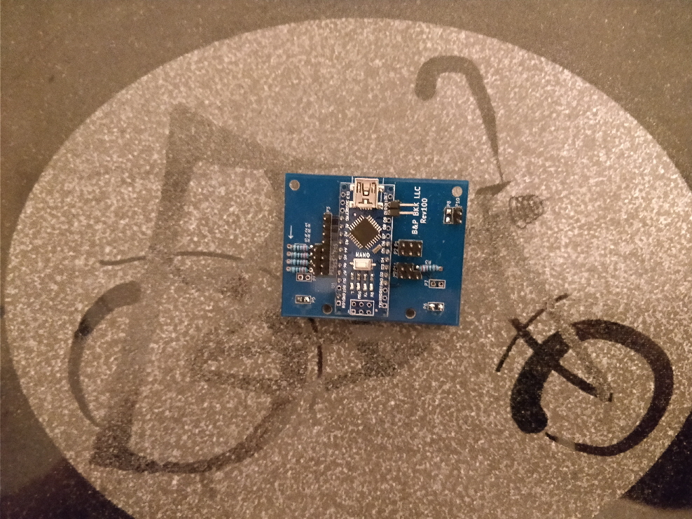 Plate & Ball PCBA R100
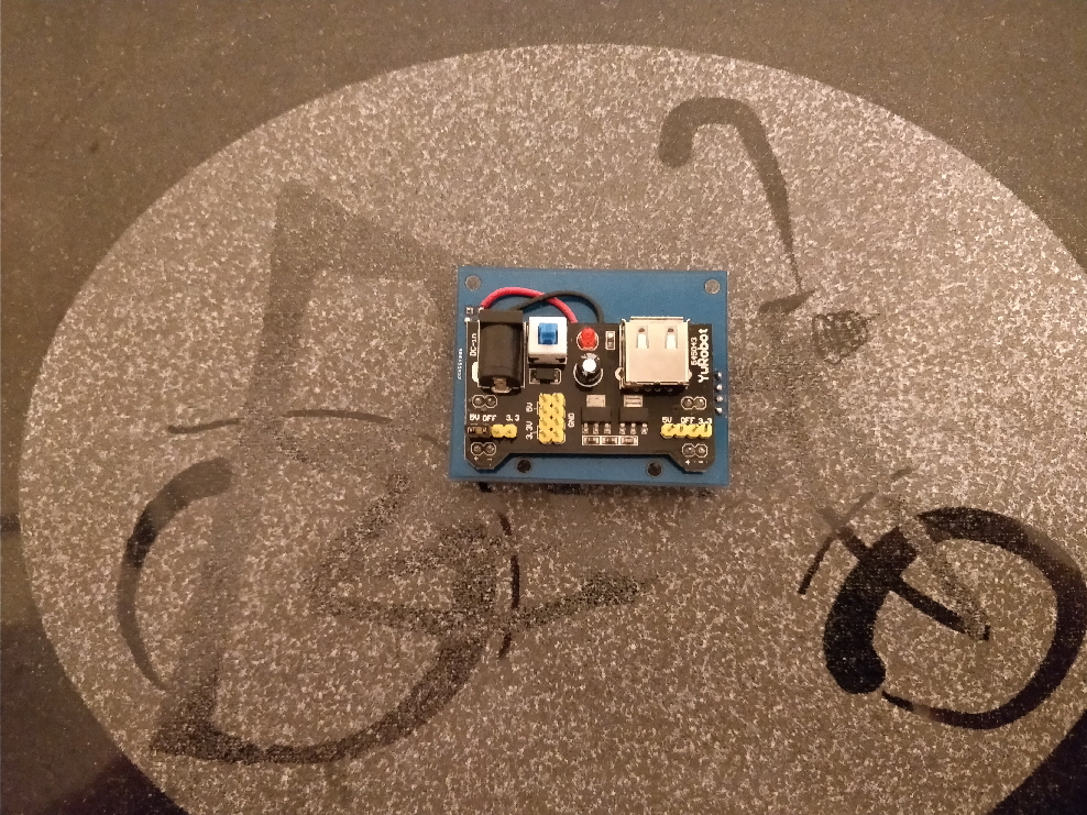 Plate & Ball PCBA R100
 Plate & Ball PCBA R102
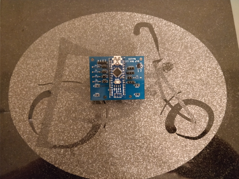 Plate & Ball PCBA R103
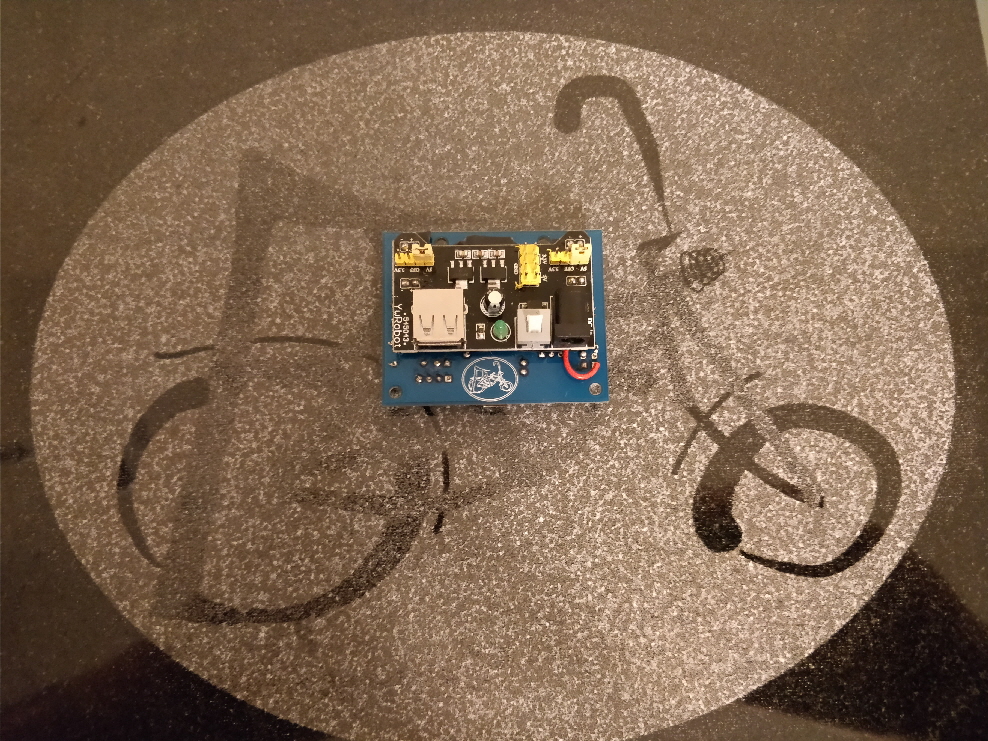 Plate & Ball PCBA R103
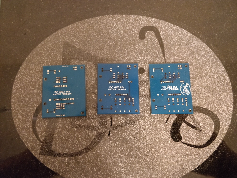 Progression of Plate & Ball PCBA's
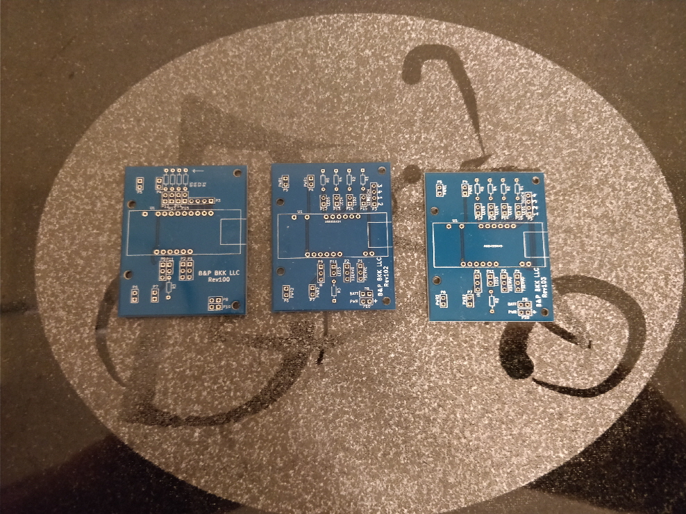 Progression of Plate & Ball PCBA's


